Introduction#
Following up on the multi-drone simulation setup covered in the previous article, this article explains how to control multiple drones using Offboard mode in ROS2. Multi-drone simulation involves several subtle naming conventions and code details that are easy to overlook — this article covers them all. If you encounter issues during simulation, use this as a troubleshooting reference.
Communication Overview#
Multi-drone communication is more convenient in ROS2. Let’s reference the PX4 official documentation:
XRCE-DDS allows multiple clients to connect to the same agent via UDP. This is particularly useful in simulation since only one agent needs to be started.
Following the previous article, each drone instance already has an independent px4_instance number assigned, corresponding to the -i 0/1/2... flag in our launch command. There’s no need to manually assign instance numbers. Let’s now proceed to Offboard control.
Starting the Simulation#
Following the workflow from the previous article, we start two x_500 drone instances. Launch QGC ground station and Gazebo first, then open two terminals to start instances at positions (0,0) and (0,2) with px4_instance numbers 0 and 1:
# Terminal 1
cd ~/PX4-Autopilot
PX4_GZ_STANDALONE=1 PX4_SYS_AUTOSTART=4001 PX4_GZ_MODEL_POSE="0,0" PX4_SIM_MODEL=gz_x500 ./build/px4_sitl_default/bin/px4 -i 0

# Terminal 2
cd ~/PX4-Autopilot
PX4_GZ_STANDALONE=1 PX4_SYS_AUTOSTART=4001 PX4_GZ_MODEL_POSE="0,2" PX4_SIM_MODEL=gz_x500 ./build/px4_sitl_default/bin/px4 -i 1Now check the ROS2 topics:
ros2 topic listThis shows the published topics from both PX4 instances:
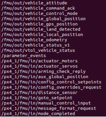
We can see that topics from both PX4 instances are successfully published. Note the naming convention — you’ll need this when writing control code:
Naming Rule: When the instance number is 0, topic names start with
/fmu/. When the instance number is ≥ 1, topic names start with/px4_i/fmu/, whereiis the instance number from the launch command. This is critical.
Starting Communication#
Now add communication for both drones. As explained above, use:
MicroXRCEAgent udp4 -p 8888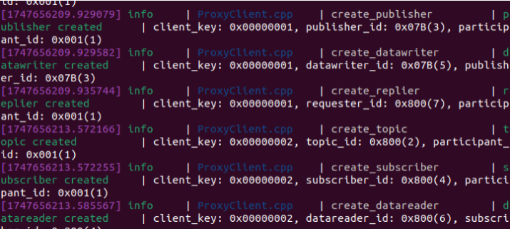
A single agent instance handles both drones. From the terminal output we can see two client IDs: 0x00000001 and 0x00000002. These correspond to the MAVLINK IDs, as explained in the official documentation:
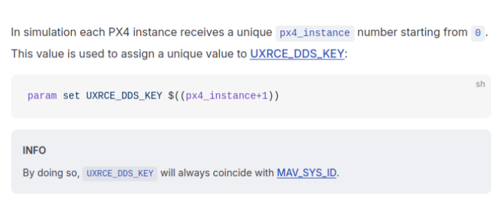
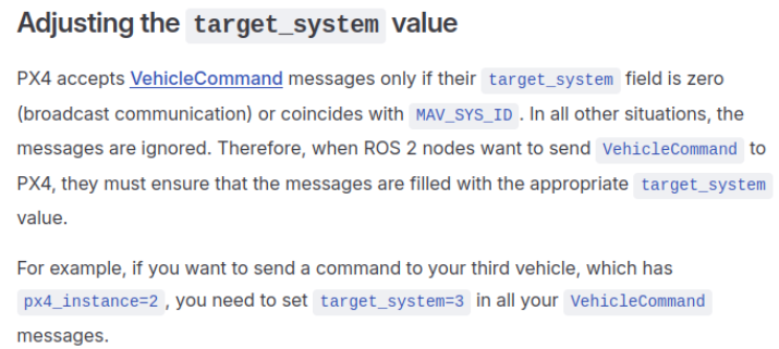
From the first table: when the agent starts, it automatically assigns UXRCE_DDS_KEY values to each instance. This value equals the MAVLINK ID, and both equal px4_instance + 1. So our drone 0 maps to 1, and drone 1 maps to 2.
From the second table: the target_system number also equals the MAVLINK ID, which is px4_instance + 1.
With these naming conventions clarified, we can now move on to the code.
Dual-Drone Offboard Code Walkthrough#
We’ll write a leader-follower formation flight controller using Offboard mode.
#include <px4_msgs/msg/offboard_control_mode.hpp>
#include <px4_msgs/msg/trajectory_setpoint.hpp>
#include <px4_msgs/msg/vehicle_command.hpp>
#include <rclcpp/rclcpp.hpp>
#include <stdint.h>

#include <chrono>
#include <cmath>
#include <iostream>

using namespace std::chrono;
using namespace std::chrono_literals;
using namespace px4_msgs::msg;Include headers and declare namespaces. px4_msgs is the most heavily used PX4 message package — we primarily use three types: OffboardControlMode, TrajectorySetpoint, and VehicleCommand.
class MultiOffboardControl : public rclcpp::Node
{
public:
    MultiOffboardControl() : Node("multi_offboard_control")
    {
        offboard_control_mode_publisher_uav0_ = this->create_publisher<OffboardControlMode>("/fmu/in/offboard_control_mode", 10);
        trajectory_setpoint_publisher_uav0_ = this->create_publisher<TrajectorySetpoint>("/fmu/in/trajectory_setpoint", 10);
        vehicle_command_publisher_uav0_ = this->create_publisher<VehicleCommand>("/fmu/in/vehicle_command", 10);

        offboard_control_mode_publisher_uav1_ = this->create_publisher<OffboardControlMode>("/px4_1/fmu/in/offboard_control_mode", 10);
        trajectory_setpoint_publisher_uav1_ = this->create_publisher<TrajectorySetpoint>("/px4_1/fmu/in/trajectory_setpoint", 10);
        vehicle_command_publisher_uav1_ = this->create_publisher<VehicleCommand>("/px4_1/fmu/in/vehicle_command", 10);

        offboard_setpoint_counter_ = 0;
        time_start_ = this->get_clock()->now();

        auto timer_callback = [this]() -> void {
            if (offboard_setpoint_counter_ == 10 || offboard_setpoint_counter_ % 50 == 0) {
                this->publish_vehicle_command_uav0(VehicleCommand::VEHICLE_CMD_DO_SET_MODE, 1, 6);
                this->arm_uav0();
                this->publish_vehicle_command_uav1(VehicleCommand::VEHICLE_CMD_DO_SET_MODE, 1, 6);
                this->arm_uav1();
            }

            publish_offboard_control_mode_uav0();
            publish_trajectory_setpoint_uav0();
            publish_offboard_control_mode_uav1();
            publish_trajectory_setpoint_uav1();

            if (offboard_setpoint_counter_ < 11) {
                offboard_setpoint_counter_++;
            }
        };
        timer_ = this->create_wall_timer(100ms, timer_callback);
}Define the MultiOffboardControl class and constructor, naming the node "multi_offboard_control". The constructor creates publishers for both drone instances’ ROS2 topics with a queue size of 10. This is where the topic naming rule matters: drone 0 uses /fmu/ prefix, drone 1 uses /px4_1/fmu/ prefix. Pay close attention here.
A 100ms timer is set up: on the 10th cycle it arms both drones, and thereafter it continuously publishes Offboard control commands.
Note: The timer frequency must meet the Offboard minimum of 2Hz. Our 100ms (10Hz) satisfies this requirement. Lower frequencies combined with position-only control may result in larger trajectory deviations.
    void arm_uav0() { publish_vehicle_command_uav0(VehicleCommand::VEHICLE_CMD_COMPONENT_ARM_DISARM, 1.0); }
    void disarm_uav0() { publish_vehicle_command_uav0(VehicleCommand::VEHICLE_CMD_COMPONENT_ARM_DISARM, 0.0); }
    void arm_uav1() { publish_vehicle_command_uav1(VehicleCommand::VEHICLE_CMD_COMPONENT_ARM_DISARM, 1.0); }
    void disarm_uav1() { publish_vehicle_command_uav1(VehicleCommand::VEHICLE_CMD_COMPONENT_ARM_DISARM, 0.0); }

private:
    rclcpp::TimerBase::SharedPtr timer_;
    rclcpp::Publisher<OffboardControlMode>::SharedPtr offboard_control_mode_publisher_uav0_;
    rclcpp::Publisher<TrajectorySetpoint>::SharedPtr trajectory_setpoint_publisher_uav0_;
    rclcpp::Publisher<VehicleCommand>::SharedPtr vehicle_command_publisher_uav0_;
    rclcpp::Publisher<OffboardControlMode>::SharedPtr offboard_control_mode_publisher_uav1_;
    rclcpp::Publisher<TrajectorySetpoint>::SharedPtr trajectory_setpoint_publisher_uav1_;
    rclcpp::Publisher<VehicleCommand>::SharedPtr vehicle_command_publisher_uav1_;
    uint64_t offboard_setpoint_counter_;
    rclcpp::Time time_start_;
float leader_position_[3] = {0.0, 0.0, -5.0};arm_uav0() and disarm_uav0() arm and disarm drone 0 respectively — the same commands we saw in the PX4 terminal in the previous article.
For trajectory generation, we use the simplest leader-follower algorithm: the leader’s initial position is (0, 0, -5). Drone 0 (leader) flies in a circular pattern at altitude 5m, radius 5m, period 20s. Drone 1 (follower) tracks the leader’s position with a fixed offset — 2m behind and 2m to the right.
Each drone instance has three corresponding functions: publish_offboard_control_mode_uav0/1(), publish_trajectory_setpoint_uav0/1(), and publish_vehicle_command_uav0/1(), corresponding to the three main message types. Let’s examine each:
    void publish_offboard_control_mode_uav0()
    {
        OffboardControlMode msg{};
        msg.position = true;
        msg.velocity = false;
        msg.acceleration = false;
        msg.attitude = false;
        msg.body_rate = false;
        msg.timestamp = this->get_clock()->now().nanoseconds() / 1000;
        offboard_control_mode_publisher_uav0_->publish(msg);
}publish_offboard_control_mode_uav0() sends the control mode to drone 0. Setting msg.position = true enables position control mode in Offboard. Other modes (velocity, acceleration, attitude, body rate) are set to false. For more advanced flight control algorithm research, modify these flags to use multiple control modes.
    void publish_trajectory_setpoint_uav0()
    {
        auto now = this->get_clock()->now();
        double t = (now - time_start_).seconds();
        const double radius = 5.0;
        const double period = 20.0;
        double omega = 2.0 * M_PI / period;

        TrajectorySetpoint msg{};
        msg.position = {
            static_cast<float>(radius * std::cos(omega * t)),
            static_cast<float>(radius * std::sin(omega * t)),
            -5.0f
        };
        msg.yaw = -omega * t;
        msg.timestamp = this->get_clock()->now().nanoseconds() / 1000;
        trajectory_setpoint_publisher_uav0_->publish(msg);

        leader_position_[0] = msg.position[0];
        leader_position_[1] = msg.position[1];
        leader_position_[2] = msg.position[2];
        RCLCPP_INFO(this->get_logger(), "uav0 position: x=%f, y=%f, z=%f",
                    leader_position_[0], leader_position_[1], leader_position_[2]);
}publish_trajectory_setpoint_uav0() sends trajectory setpoints to drone 0 (the leader), which flies in a circle at constant angular velocity.
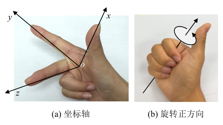
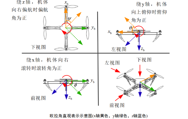
A note on msg.yaw: this represents the quadrotor’s yaw angle using Euler angle attitude representation. Quadrotors use the NED right-hand coordinate system with counterclockwise as the positive rotation direction. The three Euler angles — roll, pitch, and yaw — represent the drone’s orientation. In both drones’ trajectory code, yaw is set to align the drone with the flight path tangent/normal. Below are Euler angle reference diagrams:
    void publish_vehicle_command_uav0(uint16_t command, float param1 = 0.0, float param2 = 0.0)
    {
        VehicleCommand msg{};
        msg.param1 = param1;
        msg.param2 = param2;
        msg.command = command;
        msg.target_system = 1;
        msg.target_component = 1;
        msg.source_system = 1;
        msg.source_component = 1;
        msg.from_external = true;
        msg.timestamp = this->get_clock()->now().nanoseconds() / 1000;
        RCLCPP_INFO(this->get_logger(), "uav0 command: %u, param1=%f, param2=%f, target_system=%u",
                    command, param1, param2, msg.target_system);
        vehicle_command_publisher_uav0_->publish(msg);
}publish_vehicle_command_uav0() sends vehicle commands to drone 0. Two parameters deserve attention: msg.target_system follows the px4_instance + 1 rule (drone 0 → 1, drone 1 → 2, etc.). msg.from_external must be true since we’re using external Offboard control mode.
    void publish_offboard_control_mode_uav1()
    {
        OffboardControlMode msg{};
        msg.position = true;
        msg.velocity = false;
        msg.acceleration = false;
        msg.attitude = false;
        msg.body_rate = false;
        msg.timestamp = this->get_clock()->now().nanoseconds() / 1000;
        offboard_control_mode_publisher_uav1_->publish(msg);
    }

    void publish_trajectory_setpoint_uav1()
    {
        const float offset_x = 2.0;
        const float offset_y = 2.0;
        const float offset_z = 0.0;

        TrajectorySetpoint msg{};
        msg.position = {
            leader_position_[0] + offset_x,
            leader_position_[1] + offset_y,
            leader_position_[2] + offset_z
        };
        msg.yaw = -std::atan2(msg.position[1], msg.position[0]);
        msg.timestamp = this->get_clock()->now().nanoseconds() / 1000;
        RCLCPP_INFO(this->get_logger(), "uav1 setpoint: x=%f, y=%f, z=%f",
                    msg.position[0], msg.position[1], msg.position[2]);
        trajectory_setpoint_publisher_uav1_->publish(msg);
    }

    void publish_vehicle_command_uav1(uint16_t command, float param1 = 0.0, float param2 = 0.0)
    {
        VehicleCommand msg{};
        msg.param1 = param1;
        msg.param2 = param2;
        msg.command = command;
        msg.target_system = 2;
        msg.target_component = 1;
        msg.source_system = 1;
        msg.source_component = 1;
        msg.from_external = true;
        msg.timestamp = this->get_clock()->now().nanoseconds() / 1000;
        RCLCPP_INFO(this->get_logger(), "uav1 command: %u, param1=%f, param2=%f, target_system=%u",
                    command, param1, param2, msg.target_system);
        vehicle_command_publisher_uav1_->publish(msg);
    }
};Drone 1’s (follower) three functions mirror the leader’s, with the topic prefix changed to /px4_1/fmu/, target_system set to 2, and trajectory set to the leader’s current position plus a fixed offset of (2.0, 2.0, 0.0) for rear-right formation flight.
int main(int argc, char *argv[])
{
    std::cout << "Starting multi offboard control node..." << std::endl;
    setvbuf(stdout, NULL, _IONBF, BUFSIZ);
    rclcpp::init(argc, argv);
    rclcpp::spin(std::make_shared<MultiOffboardControl>());
    rclcpp::shutdown();
    return 0;
}The main() function: rclcpp::init initializes the ROS2 environment, rclcpp::spin runs the multi_offboard_control node, and rclcpp::shutdown cleans up on exit.
After compiling and running as described in the previous article, both drones follow the programmed trajectories and maintain formation, confirming the dual-drone formation simulation is working correctly. Below is the simulation video:
Video 1: Dual drones performing circular formation flight around a fixed point, 20-second period
Summary#
Drone formation simulation is more convenient in ROS2, primarily due to integrated communication — no need to manually add communication for each drone instance. However, subtle naming convention mistakes often cause failures: ROS2 topic naming rules, MAVLINK ID rules, and target_system rules. This article has covered these conventions with reference to PX4 official documentation.
For clarity, this article used a simple two-drone leader-follower formation. Real-world applications demand far more sophisticated approaches. In a later article, we introduce Distributed Control & Second-Order Consensus, using LMI-based gain synthesis to achieve more robust multi-drone formation control. We look forward to seeing what you build.
Thank you for reading. Feedback, corrections, and suggestions are always welcome.
References#
- BUAA Reliable Flight Control Group
- PX4 Official Documentation: ROS2 Multi-Vehicle Simulation ↗