Introduction#
In the previous real-hardware article, we covered flashing the onboard computer. This guide builds on that work to walk through the complete ROS2 + PX4 real-flight takeoff workflow, using the onboard computer together with the low-level flight controller. If you’re new to PX4 simulation, start with the ROS2+PX4 Simulation Setup Guide.
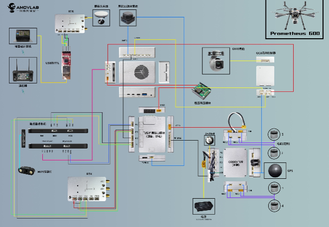
The author uses an AMOVLAB JCV-600 research quadrotor (with a CodevDynamics Codev-autopilot based on PX4) and an Nvidia Jetson Orin NX as the onboard computer for ROS2 control. Readers can follow this tutorial and adapt it to their own hardware.
Required hardware (adjust according to your setup):
- A complete drone kit or a drone with a self-flashed flight controller
- A pair of telemetry radios
- A local PC and an onboard computer
- Appropriate connecting cables (refer to the I/O port specifications of your onboard computer and drone)
- Pinout diagrams / manuals for the relevant drone interfaces
Process Overview#
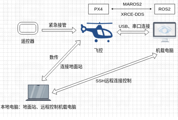
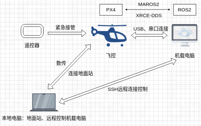
The diagram below gives a high-level summary of the real-flight takeoff workflow used in this article. First, establish a stable connection between the ground station and the flight controller via the telemetry radio, ensuring that sensor data, GPS signals, and RC commands are transmitted properly. Next, the onboard computer communicates with the flight controller over a serial port — install drivers, configure permissions, and match baud rates. After completing pre-flight checks in the ground station, connect to the onboard computer remotely via SSH, launch the MAVROS2 node to bridge ROS2 and PX4, and finally control the drone in Offboard mode. Throughout the entire process, keep the telemetry link active, monitor ground station data, and be ready to take manual control at any moment to guarantee flight safety.
Establishing a Connection with the Ground Station#
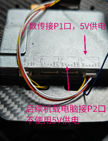
Throughout the entire experiment, PX4 requires a stable connection to a ground station. The author uses a pair of RFD900x telemetry radios. The radio on the drone connects to the flight controller’s I/O port (GND, RX-to-TX, TX-to-RX cross-connected); the flight controller provides a 5V power pin for the radio (internal power distribution is already handled).
On your local PC, open QGroundControl. Under “Application Settings” -> “Comm Links” -> “Add New Link”, set Type to “Serial”, select the serial port containing “USB0”, and use the default baud rate of 57600. Once connected, the “ACT” LED on both radios stays solid green (power normal) and the “COM” LED blinks (link established). The ground station should display the drone’s status.
Connecting the Onboard Computer to the Flight Controller#
First, connect the flight controller to your PC via USB-TypeC. In the Parameters page, add a MAVLINK instance for the onboard computer (the default serial port is usually TELEM2):
MAV_1_CONFIG = TELEM2
MAV_1_MODE = Onboard
MAV_1_RATE = 115200Three connection methods are described below.
Method 1: USB-TTL Cable#
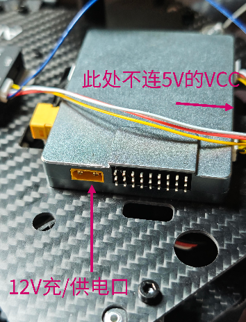
Use the flight controller’s TELEM2 interface, which provides six pins: VCC (5V), TX, RX, PWM, GPIO, and GND. Connect the USB end to the onboard computer, and use Dupont-to-terminal wires to cross-connect GND, TX, and RX between the flight controller and the adapter. Do not supply power through this connection. The onboard computer should be powered separately from the reserved 12V power port.
# Check USB connection
lsusb
ls -l /dev/tty*
# You should see a CH340 USB-Serial adapter and /dev/ttyS0

# Add user to the dialout group
sudo usermod -a -G dialout $USERDownload and compile the CH340 driver:
sudo apt install build-essential git linux-headers-$(uname -r)
git clone https://github.com/juliagoda/CH341SER
cd CH341SER
make && sudo make install
sudo insmod ch341.ko
sudo cp ch341.ko /lib/modules/$(uname -r)/kernel/drivers/usb/serial/
sudo depmod -a
echo "ch341" | sudo tee /etc/modules-load.d/ch341.confCreate the udev rule at /etc/udev/rules.d/99-ch341.rules:
SUBSYSTEM=="tty", ATTRS{idVendor}=="1a86", ATTRS{idProduct}=="7523", MODE="0666", SYMLINK+="ttyCH341"sudo udevadm control --reload-rules && sudo udevadm trigger
ls -l /dev/ttyCH341 # Verify the driver is installedTest communication (MAVLINK garbled output means success):
stty -F /dev/ttyUSB0 115200 raw -echo
cat /dev/ttyUSB0If you encounter issues with the USB-TTL connection method above, refer to the following link for driver installation guidance: https://blog.csdn.net/qq_52102933/article/details/126839474 ↗
Method 2: UART Serial Cable#
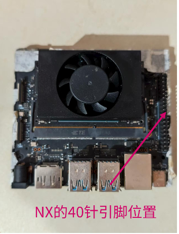
The Jetson Orin NX has a 40-pin UART header, where Pin 8 (TX) and Pin 10 (RX) serve as the default UART1 debug port. We will use UART2 for this connection: Pin 14 (RX), Pin 12 (TX), Pin 6 (GND). Do not connect VCC; power the onboard computer separately.
# List available UART devices
ls /dev/ttyTHS*

# If ttyTHS1 is missing, edit /boot/extlinux/extlinux.conf
# Append console=ttyTHS1,115200 to the kernel boot line
sudo reboot

# Configure permissions and baud rate
sudo usermod -aG dialout $USER
stty -F /dev/ttyTHS1 115200 raw -echo
cat /dev/ttyTHS1 # Test communicationMethod 3: USB-TypeC Cable#
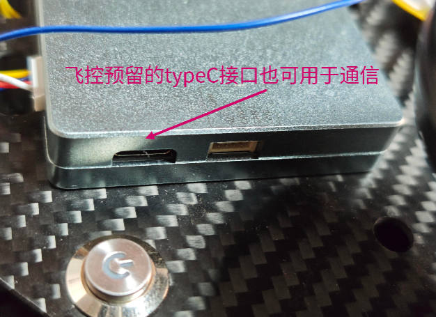
On the author’s JCV-600, the TypeC port can connect directly to the onboard computer (for reference only; may not apply to all hardware).
lsusb  # Should show ID 26ac:0032 The Autopilot PX4 CODEV DP1000
sudo usermod -aG dialout $USER
stty -F /dev/ttyACM0 115200 raw -echo
cat /dev/ttyACM0 # Test communicationPre-Flight Checks with the Ground Station#
Perform the following checks on the “Vehicle Setup” page:
Sensor calibration: accelerometer, gyroscope, magnetometer, and level-horizon calibration; verify GPS signal quality (typically 6 or more satellites).
Parameter checks:
SYS_COMPANION = 921600(ROS2 communication baud rate)MAV_1_CONFIG = TELEM2(matches the serial port connected to the onboard computer)BAT_*parameters match the actual battery specifications- Verify that the emergency stop switch functions correctly
- Confirm that the RC transmitter channel mapping is correct
Important: When using Offboard mode in real flights, always be ready to take over manually with the RC transmitter to ensure safety. Once all checks are complete, QGroundControl should display “Ready for Fly”.
Remote Connection to the Onboard Computer via SSH#
SSH (Secure Shell) is a network security protocol that provides secure remote access and file transfer through encryption and authentication. Because the onboard computer is attached to the drone and flies with it while issuing real-time ROS control commands to the flight controller, we cannot operate it directly. Instead, we use SSH to connect from the local PC to the remote onboard computer, enabling remote control of the flight controller through the onboard computer.
On the onboard computer, enable SSH and set it to start automatically at boot:
sudo systemctl start ssh
sudo systemctl enable ssh
sudo systemctl status ssh # Should show active (running)Ensure both computers are on the same local network. Using a personal hotspot is recommended to avoid client isolation on public networks. Look up the IP address:
ifconfig  # Look for output such as inet 10.192.90.46 netmask 255.255.0.0 broadcast 10.192.255.255
# Here 10.192.90.46 is the IPv4 address; netmask and broadcast are the subnet mask and broadcast address respectively
# Verify the IPv4 addresses of both computers to ensure they are on the same large subnet
ping 10.192.90.46 # From the local PC, ping the onboard computer to verify connectivitySSH connection:
ssh jetson@10.192.90.46  # First time: type "yes" to confirm, then enter the password
# Once the terminal prompt changes to jetson@ubuntu:~$, the connection is successful
# Type exit to close the SSH sessionOffboard Mode Control with MAVROS#
In the simulation articles we used MicroXRCEAgent for ROS2-PX4 communication. The author’s flight controller firmware includes MAVROS (rather than the XRCE middleware). MAVROS is a crucial tool bridging ROS and the MAVLINK protocol. The MAVROS2 package for ROS2 is still under active development and maintenance, but it is already usable for simple tasks.
In the future, the author plans to explore development with the XRCE middleware, which will require re-flashing the PX4 firmware. Update: ROS2+PX4 Drone Swarm Real-Flight (Part 3): Deploying the UXRCE-DDS Middleware (with Pixhawk 6C)
Installing MAVROS2#
sudo apt install ros-humble-mavros ros-humble-mavros-msgs

# Install the GeographicLib geographic datasets (required dependency)
wget https://raw.githubusercontent.com/mavlink/mavros/master/mavros/scripts/install_geographiclib_datasets.sh
chmod +x install_geographiclib_datasets.sh
sudo ./install_geographiclib_datasets.shCreating the Offboard Node#
cd ~/ros2_ws/src
ros2 pkg create --build-type ament_python offboard_control \
    --dependencies rclpy geometry_msgs mavros_msgs
cd offboard_control/offboard_control
touch simple_offboard.py && chmod +x simple_offboard.pyComplete source code of simple_offboard.py (Offboard takeoff and hover at 5 meters):
#!/usr/bin/env python3

import rclpy
from rclpy.node import Node
from rclpy.clock import Clock
from geometry_msgs.msg import PoseStamped
from mavros_msgs.msg import State
from mavros_msgs.srv import CommandBool, SetMode

class SimpleOffboard(Node):

    def __init__(self):
        super().__init__('simple_offboard')

        # mavros
        self.declare_parameter('mavros_ns', '/mavros')
        self.mavros_ns = self.get_parameter('mavros_ns').get_parameter_value().string_value

        # publishers
        self.local_pos_pub = self.create_publisher(
            PoseStamped,
            f'{self.mavros_ns}/setpoint_position/local',
            10
        )

        # subscribers
        self.state_sub = self.create_subscription(
            State,
            f'{self.mavros_ns}/state',
            self.state_callback,
            10
        )

        # service clients
        self.arming_client = self.create_client(
            CommandBool,
            f'{self.mavros_ns}/cmd/arming'
        )
        while not self.arming_client.wait_for_service(timeout_sec=1.0):
            self.get_logger().info('mavros/arming service not available, waiting...')

        self.set_mode_client = self.create_client(
            SetMode,
            f'{self.mavros_ns}/set_mode'
        )
        while not self.set_mode_client.wait_for_service(timeout_sec=1.0):
            self.get_logger().info('mavros/set_mode service not available, waiting...')

        self.current_state = State()
        self.timer = self.create_timer(0.05, self.control_loop)
        self.offboard_setpoint_counter = 0
        self.last_call_time = self.get_clock().now()
        self.target_altitude = 5.0

        self.get_logger().info("Offboard Node Initialized. Waiting for MAVROS state...")

    def state_callback(self, msg):
        self.current_state = msg

    def arm_drone(self):
        self.get_logger().info("Attempting to ARM drone...")
        arm_request = CommandBool.Request()
        arm_request.value = True
        future = self.arming_client.call_async(arm_request)
        future.add_done_callback(self.arm_response_callback)

    def arm_response_callback(self, future):
        try:
            response = future.result()
            if response.success:
                self.get_logger().info("Arming successful!")
            else:
                self.get_logger().warn(f"Arming failed: {response.result}")
        except Exception as e:
            self.get_logger().error(f"Arming service call failed: {str(e)}")

    def set_offboard_mode(self):
        self.get_logger().info("Attempting to set OFFBOARD mode...")
        mode_request = SetMode.Request()
        mode_request.custom_mode = "OFFBOARD"
        future = self.set_mode_client.call_async(mode_request)
        future.add_done_callback(self.set_mode_response_callback)

    def set_mode_response_callback(self, future):
        try:
            response = future.result()
            if response.mode_sent:
                self.get_logger().info("OFFBOARD mode enabled!")
            else:
                self.get_logger().warn(f"Failed to set OFFBOARD mode.")
        except Exception as e:
            self.get_logger().error(f"SetMode service call failed: {str(e)}")

    def control_loop(self):
        now = self.get_clock().now()

        self.get_logger().info(
            f"[State] Connected: {self.current_state.connected}, "
            f"Armed: {self.current_state.armed}, "
            f"Mode: {self.current_state.mode}",
            throttle_duration_sec=1.0
        )

        pose = PoseStamped()
        pose.header.stamp = now.to_msg()
        pose.header.frame_id = "map"
        pose.pose.position.x = 0.0
        pose.pose.position.y = 0.0
        pose.pose.position.z = float(self.target_altitude)
        self.local_pos_pub.publish(pose)

        if not self.current_state.connected:
            return

        time_since_last_call = (now - self.last_call_time).nanoseconds / 1e9

        if time_since_last_call > 5.0:
            if not self.current_state.armed:
                self.arm_drone()
                self.last_call_time = now
            elif self.current_state.mode != "OFFBOARD":
                self.set_offboard_mode()
                self.last_call_time = now

def main(args=None):
    rclpy.init(args=args)
    offboard_node = SimpleOffboard()

    try:
        rclpy.spin(offboard_node)
    except KeyboardInterrupt:
        offboard_node.get_logger().info('Offboard control interrupted by user.')
    finally:
        offboard_node.destroy_node()
        rclpy.shutdown()
        print("Offboard Node Shutdown.")

if __name__ == '__main__':
main()Add the following to entry_points in setup.py:
'console_scripts': [
    'simple_offboard = offboard_control.simple_offboard:main',
],Build:
cd ~/ros2_ws
colcon build --symlink-install --packages-select offboard_control
source install/setup.bashTakeoff#
With all hardware and software preparations complete, execute the full takeoff procedure:
- Connect the drone to the ground station via the telemetry radio
- Connect the onboard computer to the flight controller using any of the three methods
- Complete the pre-flight checks in the ground station
- Use SSH to remotely connect from the local PC to the onboard computer
- In the SSH terminal, execute:
# Activate the ROS2 environment
source /opt/ros/humble/setup.bash
source ~/ros2_ws/install/setup.bash

# Launch the MAVROS2 node (serial port and baud rate must match the flight controller configuration)
ros2 run mavros mavros_node --ros-args -p fcu_url:="serial:///dev/ttyACM0:115200"
# When you see [INFO] [mavros]: FCU connection established, the link is up

# Launch the Offboard control node
ros2 run offboard_control simple_offboardAt this point you should see the drone arm, take off, and ascend to 5 meters. Due to the inherent risk of Offboard mode, always be ready to take over with the RC transmitter.
Summary#
Practice makes perfect — get hands-on and iterate. This article has presented one complete workflow: from telemetry radio connection, through three hardware connection methods between the onboard computer and flight controller, pre-flight checks, SSH remote access, and finally MAVROS2 Offboard takeoff. Corrections and feedback are welcome. Thank you for reading!
References#
- AMOVLAB JCV-600 User Manual ↗
- PX4 Official Documentation ↗
- ROS2+PX4 Drone Swarm Real-Flight (Part 3): Deploying the UXRCE-DDS Middleware